There are many different ways to generate 3d models. Software like Blender gives you a pile of tools and modifiers with which you can model almost any object. Then you have your sculpting editors with which you can model complex organic shapes, as if you were modeling with clay. Finally, you have procedural modeling tools with which you can generative repetitive 3d geometry using simple rules.
I have done my fair share of playing around with Blender, but I wanted to play around with a 3d editor which works a bit more immediately, like Photoshop or Affinity Photo. In those programs, any changes you make are non-destructive – you don’t need hit Ctrl + Z multiple times to rewind back through the edits you made. Instead, all edits are retained in a stack, and any changes you make to the edit stack rerenders the resulting picture in full.
This kind of workflow is particularly suitable for procedural modeling methods, as the current set of rules can be re-evaluated from scratch to regenerate the model for the user. In this post, I will focus on implementing this sort of workflow using shape grammars, which are a procedural modeling method suitable for constructing 3d models of buildings. There are lots of existing papers and work around text-based shape grammars available. One of my goals in this post, however, was to take one of the existing text-based systems and build a node graph editor around the grammar.
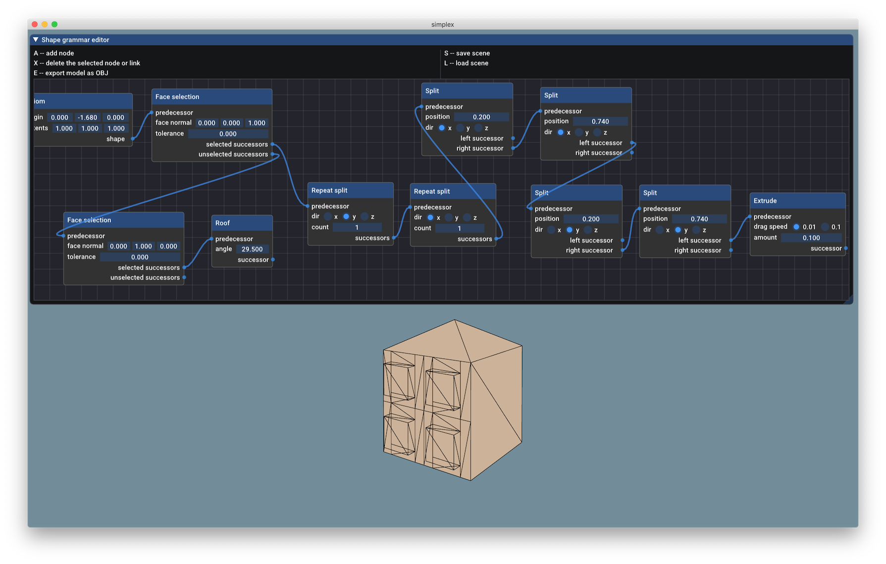
The node graph editor for manipulating shape grammars. The tool looks admittedly quite "homemade", but it works!
Let’s start by diving in to shape grammars.
Shape grammars
A shape grammar is a hierarchy of named 3d shapes, known as symbols, and the operations that produce them, known as production rules. In a shape grammar, 3d shapes, referred to by symbols such as floor and window, are created by applying production rules, such as repeat split, on a symbol, replacing that symbol with a new one, known as a successor. A shape grammar is a hierarchy, because it starts with a coarse, high-level shape, such as a cube, and refines it, by applying successive production rules on the successor shapes to produce the final model.
3d grammars are a hierarchy just like grammars in linguistics. For instance, the following grammar for a simple sentence,
sentence    -> subject | verb-phrase | object
subject     -> "I" | "Visual Studio"
verb-phrase -> adverb verb | verb
adverb      -> "uneasily"
verb        -> "like" | "compiles"
object      -> noun | "the" noun | "a" noun
noun        -> "C++" | "code"
will generate sentences such as “I uneasily like C++” and “Visual Studio compiles the code”. This grammar starts with the high-level structure of a sentence, containing the symbols subject, verb-phrase, and object, and refines it by specifying what the structure of the verb-phrase and object are, and then specifies the concrete words a noun, verb and subject contain. It is a hierarchy of symbols, much like a shape grammar.
One particular shape grammar system is well-described in the paper Procedural Modeling of Buildings (2006) by Müller et al. They develop a text-based language for describing buildings, and their system is used in the Esri CityEngine software. The paper is worth taking a look at, since the authors give you a good overview of the complete textual system they developed by showing its use in many different examples.
Let’s take a closer look at how a production rule in a shape grammar works, using examples in the spirit of the work by Müller et al. The following details will be important later on, when the immediate mode editing features are developed.
A production rule takes as input a 3d shape, known as a predecessor, and replaces it with any number of output (successor) shapes. In text, this can be represented as
predecessor_name -> production_rule { successor_name }
Using this notation, we can generate a set of tiles from a quad. Let’s use the so-called repeat split operation. It takes a predecessor shape, splits it along the given axis a given number of times:
quad -> repeat_split(Y, 4) { rectangles }
rectangles -> repeat_split(X, 4) { tiles }
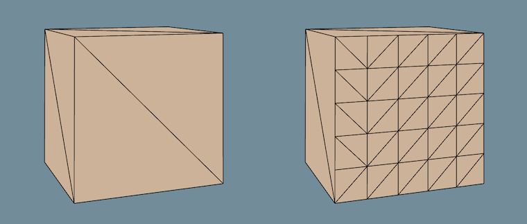
Before and after tiling a quad along the vertical and horizontal axes.
As the shape grammar is evaluated, a shape grammar configuration is used to retain the current state of the grammar. For instance, when a predecessor shape is replaced by successor shape, the predecessor is marked as inactive in the configuration, rather than being outright deleted. Likewise, each new successor shape is marked as active in the configuration. Thus, the full construction history of the final 3d shape is available in the configuration. The configuration can be used later on for contextual queries during the editing process.
Non-destructive node graph editor
Now that we have an overview of how shape grammars work, let’s build a UI and a responsive editor on top of them.
Node graphs
It is quite common in most 3d editors to use node graphs for editing the scene and material configuration. Node graphs are used since they have some advantages over textual configuration. Not only are visual tools easier to play around with, they can also prevent some classes of errors which happen in a textual configuration language, for programmers and non-programmers alike.
Let’s take a look at one possible graphical representation of a shape grammar, using the already mentioned repeat split production rule. It takes a predecessor shape, splits it n times along the user-specified axis, and produces n + 1 successor shapes. We can express this operation as a simple graph:
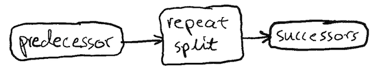
Hooray for beautifully hand-drawn graph diagrams.
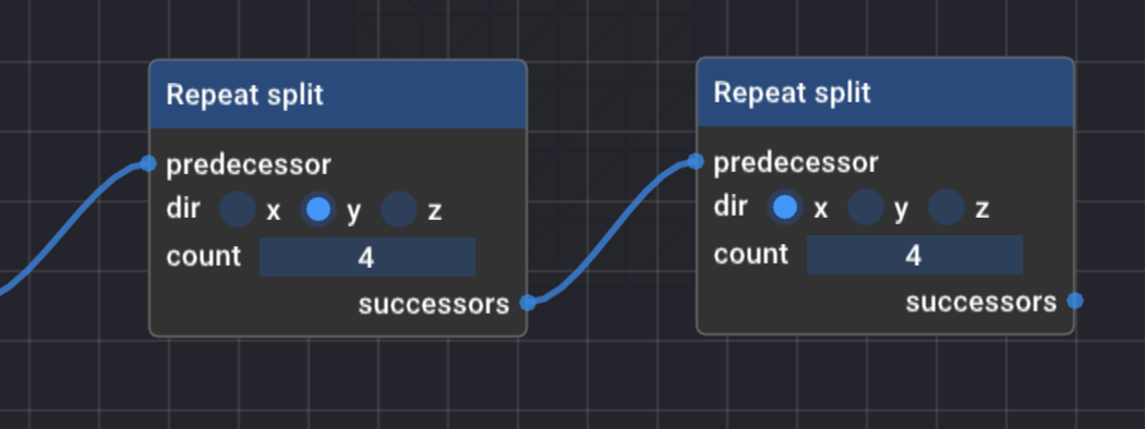
Converting our earlier tiling grammar example into a graph consists of chaining our repeat split graph nodes:
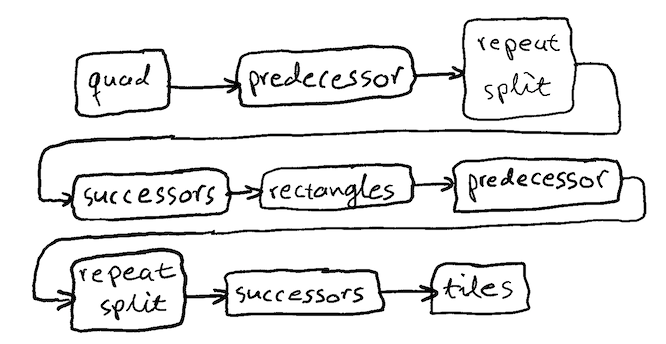
In the graph-based representation, we can actually leave the named symbol nodes completely out, and let the shapes “flow” along the edges between the predecessor and successor nodes. This node-based UI is a representation of the tiling example shape flow.
By manipulating the UI, you manipulate the underlying shape flow graph, which controls how shapes flow between production rules. When you change a node’s state, the entire shape flow is re-evaluated, and as a result you can see how the final model changes every time you make a change in the node graph.
The paper Procedural Modeling of Buildings defines a number of sophisticated production rules. The production rules they define can be broadly categorized as follows: axioms, refinement, divergent, and filter rules. My node-based editor only has a few of the paper’s production rules implemented, but we can take a look at the ones that are implemented in their categories.
Axioms
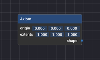
The axiom node is a unique production rule in this framework, because it doesn’t take a predecessor. All shape grammars have to start with some sort of shape, and the axiom node is the rule which defines which shape to start with. The shape can be a simple hard-coded shape, such as a quad, or it can come from an external 3d model. Currently, the axiom just produces a configurable cube.
Refinement rules
Refinement rules take a single predecessor shape, and replace it with multiple successor shapes at once. The refinement rules present in the editor are extrude, roof, and repeat split.
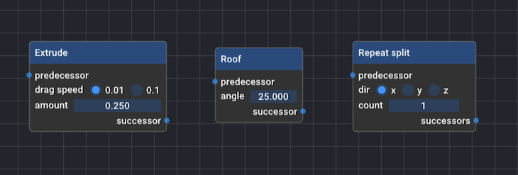
The extrude and roof nodes are examples of production rules which take the input shape, and essentially replace it with an entirely new 3d model. In the case of the extrude node, the input is replaced with a 3d extrusion of the input. And the roof node essentially places a hip roof over the input shape. The repeat split node replaces the input shape with successors that resembles the input, but split into multiple subpolygons.
Diverging rules
Only one diverging rule exists in the editor: the split node. Like the repeat split refinement rule, it takes an input shape, splits along a user-specified axis and produces multiple (two) successors: one successor for the left-hand side, and one successor for the right-hand side result.
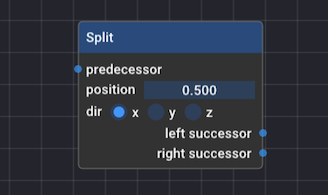
The key difference is that this rule lets you discriminate based on the successors – you can refine the left and right-hand side according to different rules, unlike the other refinement rules.
Filters
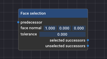
The filter node is a rule which lets you select shapes. Given a range of input shapes (such as the output of a refinement rule), it discriminates between shapes which were selected and those that remained unselected. The rule doesn’t do anything to the shapes themselves. The editor currently only has a face selection filter implemented, which let’s you choose faces based on their spatial orientation.
Editor view
The goal of the editor is to show the final model described by the grammar, as well as preview any changes being made to it as quickly as possible.
Showing the final model isn’t a particularly difficult feat – the full evaluation of the shape grammar can be performed from scratch in a few milliseconds, which means that we can regenerate the entire model during a single frame.
In order to preview changes being made to the node graph editor, let’s return very briefly to the already mentioned shape grammar configuration, which was the data structure where all active and inactive shapes produced by our shape grammar were stored. It is now very easy to selectively hide all successor shapes of a specific node in the editor view, since we have all the shapes produced by each step in our grammar. We can also preview what the resulting successors of a single node would look like.
The node-based workflow retains the full “edit state” of the final model, and let’s us tweak any values of an existing node. Just like the edit state of the photo editors mentioned in the beginning!
What else?
There’s almost an infinite amount of exploration and work which can be done with this topic.
Starting with the basics, the editor is somewhat limited at the moment with respect to the types of polygons, and types of buildings it can handle. All of the examples show models consisting entirely of quads, which are nice convex polygons. And that is all the editor can handle. The moment you introduce support for concave polygons, triangulation becomes much harder. Polygons with holes in them, and thus buildings with holes in them, are also not supported. Implementing those features would be prerequisites for generating cool structures but they are surprisingly hard to implement, at least with the time available for hobby projects.
If you have a working shape grammar system, it can be applied for city generation. The PhD thesis by Tom Kelly is especialy cool in this regard, as some of the same algorithms used for generating roofs (the straight skeleton algorithm) can be reused for generating very realistic layouts for building lots. For more, see the list of papers below!
List of papers
If some or all of the things mentioned so far seemed interesting, then you may want to check out the following papers and thesis:
- Procedural Modeling of Buildings, 2006, Müller et al.
- Advanced Procedural Modeling of Architecture, 2015, Schwarz et el.
- Procedural Modeling of Cities, 2001, Parish et al.
- Interactive Architectural Modeling with Procedural Extrusions, 2011, Kelly et al.
- Unwritten Procedural Modeling with the Straight Skeleton, 2013, PhD thesis, Tom Kelly